Capacitor chargers play a critical role in various electronic and electro-optic systems, ensuring that high voltage capacitors are charged efficiently and reliably for optimal performance. Capacitor Chargers are essential components for charging high voltage capacitors in laser systems, Pulsed UV devices and the emerging new medical science of magnetic stimulation therapy. These power supplies combine the rigors of high voltage and high current, so the design and implementation is critical to the reliability of the whole system.
This series of application notes explores the design, operation, and optimization of capacitor chargers and associated circuits. The focus will be on key principles such as capacitor charger design, basic charging circuits and additional components used in pulsed high voltage circuits. Additionally, practical solutions for mitigating issues such as voltage reversal, charging large capacitors and thermal management will be discussed. Formula’s will be provided as needed.
Capacitor Charger Design
Capacitor chargers are specifically designed as current sources for use in pulsed power applications to control the charging of high voltage capacitors. Unlike common voltage source power supplies that can be set to a specific ouptut voltage allowing the ouput current to be controlled by the load, capacitor chargers have a preset output current as the capacitor voltage rises to full charge. Controlling the output current to the capacitor as it charges from 0 voltage, essentially a short circuit to full charge simplifies the control and protection circuits of the power supply. Voltage source power supplies cannot easily charge capacitors because their short circuit protection will “fold back” the output voltage when connected to an uncharged capacitor. Capacitor chargers also include additional safety and protection circuits designed to enhance the safety of the user and faults that may occur in the power supply or high voltage output circuit.
Capacitor Charging Methods
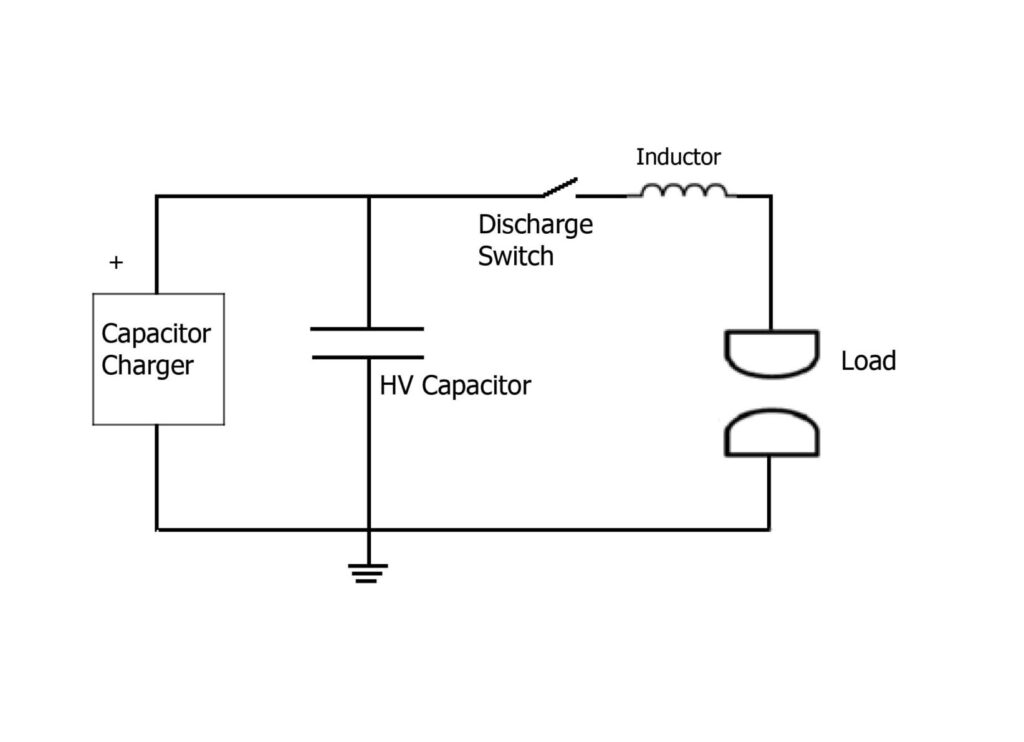
The most commonly used methods of charging capacitors in pulsed applications are full discharge and partial discharge high voltage outputs. Full discharge, as the name implies, allows the capacitor to be discharged to zero every shot. The power supply is then enabled, the capacitor is charged to the set voltage and the discharge cycle is repeated. Figure 1 is an example of a simplified pulse forming network used to deliver high peak current to a Xenon Flashlamp in a solid-state laser system. For voltages under 5kV the discharge switch is typically an SCR and for higher voltages a Thyratron is the preferred choice. Repetition rates are typically under 100Hz for flashlamp applications but pulse widths of many kilohertz can be required for Excimer Lasers.
Figure 1
Standard Formula
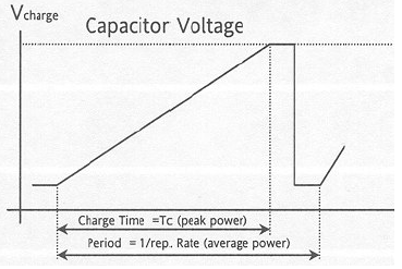
A capacitor charger has two power ratings expressed in joules per second (J/s), peak power and the average power. The peak power rating is used when calculating the charge time and the average power is used to determine the
maximum repetition rate. Figure 2 illustrates the difference between average and peak power. The simplest way to estimate the amount of energy required for an application is to use the formulas:
energy/pulse (joules) =0.5 x CV2
charge rate =energy/pulse x rep-rate
Where:
C = the capacitor in farads
V = the required charge voltage
Rep-Rate in Hertz
Figure 2
Example: The charge rate required to charge a 75uf capacitor to 1000 V with a rep-rate of 20Hz.
To account for some settling time in the high voltage circuit between pulses selecting a capacitor charger with a slightly higher charge rate is recommended. For this application the recommended capacitor charger would be the LCH1000-100 1000watts at 750V.
Partial Discharge Applications
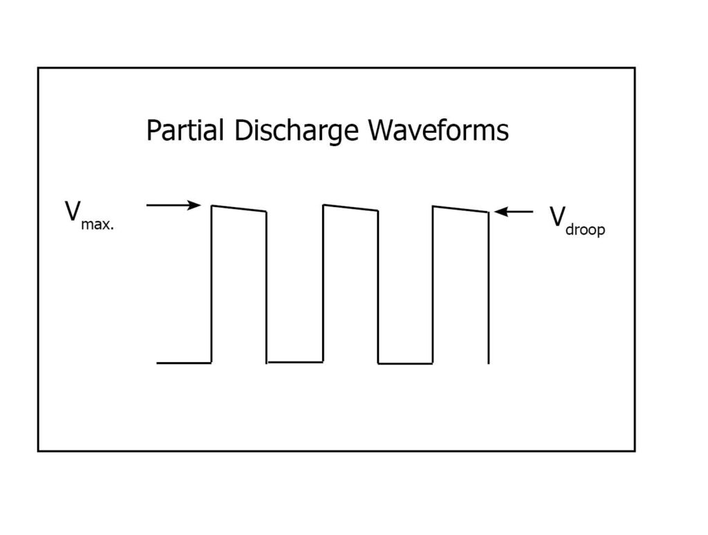
Many of today’s pulsed applications benefit from the ability to vary the pulse width of the discharge which is difficult to achieve in the standard full discharge circuit. Partial discharge circuits utilize a large amount of energy storage in the capacitor bank and vary the pulse width to the load as required. Figure 3 is a simple partial discharge circuit that uses a large storage capacitor, in some cases many farads and an IGBT driver board to pulse the load. When the capacitor charger is enabled, it charges the capacitor bank which can take a few seconds depending upon the total capacitance. Triggering the IGBT (insulated gate bipolar transistor) driver board creates square pulses to the load at the desired pulse width. Figure 4 is an example of a typical partial discharge waveform showing the initial charge voltage (V max) and the droop (V droop) in voltage as the capacitor discharges. In most applications a drop of 5 to 10% of Vmax is acceptable but with proper sizing of the capacitor bank to the desired pulse widths the drop in voltage can be longer if required. Typical pulse widths range from several hundred microseconds to tens of milliseconds.
Figure 3
In general calculating the recharge energy can be done using the formula:
E = 0.5 x C load x (Vm2 -Vd2)
Where
C= The capacitor bank in farads
Vmax = the maximum charge voltage
Vdroop =The lowest acceptable droop voltage
To size the capacitor charger, multiply the rep-rate times the energy required to refresh the capacitor.
In high-voltage (HV) capacitor charging circuits, protecting against reverse voltage is critical to ensure the safety and longevity of capacitor charger. A reverse voltage condition—whether caused by incorrect wiring, inductive kickback, or energy return from the load—can lead to catastrophic damage to power supply and associated high voltage components , semiconductors, and capacitors. Effective reverse voltage protection safeguards the circuit by blocking or safely redirecting undesired current flow. The damage threshold for voltage reversal is difficult to quantify but if a reversal causes the output current to be greater than the supply rated output current then a protection diode should be added to the load
circuit. For more information and assistance with your design please contact customer service. sales@newsourcetechnology.com | 925-462-6888
Pulsed Power Components
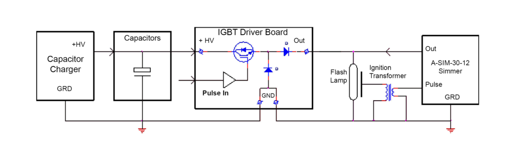
Figure 5: Typical flashlamp based pulsed system for Lasers and UV applications
Figure 5
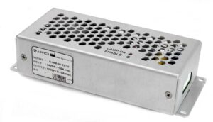
Flashlamp Simmer Power Supply
Simmer power supplies are specialized power supplies used in lamp-based laser or Intense Pulsed Light (IPL) systems to maintain a continuous, low-level current flow through the lamp between main discharge pulses. This process, called “simmering,” helps stabilize the lamp and improve its lifespan. Once the flashlamp is triggered the simmer power supply provides a trickle current (typically 100 to 150mA.) to the flashlamp between the main discharge pulses. This current maintains the arc, so the lamp does not have to be re-triggered between every pulse.
This established current path ensures a more stable and consistent flashlamp discharge during the main pulse, resulting in less variation in pulse energy. By reducing the severity of arc expansion, simmering helps to protect the flashlamp from premature failure. The simmer also supplies the ignition transformer with the primary pulse that automatically ignites the flashlamp.
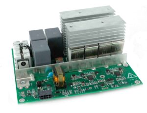
The IGBT Driver Board is designed to work with the LCH series capacitor charging power supplies in partial discharge pulsed high voltage applications. With an output capability of up to 800 amps, this board offers the designer a proven building block to drive flashlamps, pulsed UV, lasers or plasma devices. Figure 5 shows the IGBT board in a typical partial discharge lamp based system. The system’s main control circuits can trigger the gate voltage to vary the pulsewidths to the lamp. With a risetime of 10µsec., pulse widths of 50µsec. to 1ms. are acheivable.